Solid-State Lithium-Metal Batteries: Ceramic Electrolyte Dendrite Suppression and Interfacial Chemo-Mechanics
Learn how void formation, stress-driven crack propagation, and intergranular conduction drive dendrite growth in solid-state lithium-metal batteries.
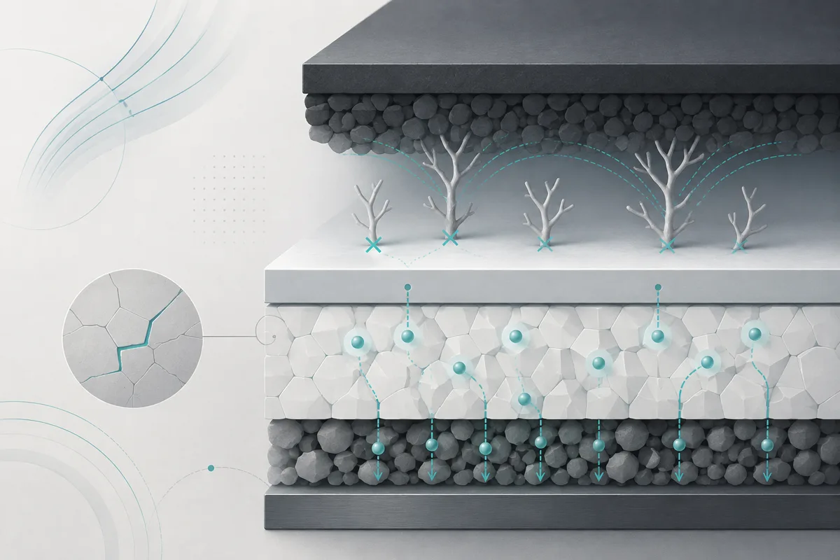
Solid-state lithium-metal batteries (SSLMBs) represent the apex architectural transition for high-energy-density electrochemical storage. By pairing a pure lithium metal anode ($\text{theoretical capacity} = 3,860\text{ mAh g}^{-1}$, electrochemical potential $-3.04\text{ V}$ vs. standard hydrogen electrode) with high-voltage transition-metal oxide cathodes (e.g., $\text{LiNi}{0.8}\text{Mn}{0.1}\text{Co}_{0.1}\text{O}_2$), cell-level specific energies exceeding $500\text{ Wh kg}^{-1}$ and volumetric energy densities beyond $1,000\text{ Wh L}^{-1}$ become theoretically viable.
The realization of these metrics depends entirely on replacing volatile, flammable organic liquid electrolytes with inorganic solid electrolytes (ISEs). Among prospective ISE classes, oxide ceramics—particularly garnet-type $\text{Li}7\text{La}3\text{Zr}2\text{O}{12}$ (LLZO, notably Al/Ta-doped variants like $\text{Li}{6.4}\text{La}3\text{Zr}{1.4}\text{Ta}{0.6}\text{O}{12}$), NASICON-type $\text{Li}{1+x}\text{Al}x\text{Ti}{2-x}(\text{PO}4)3$ (LATP), and perovskite-type $\text{Li}{3x}\text{La}{2/3-x}\text{TiO}_3$ (LLTO)—exhibit broad electrochemical stability windows, high thermal thresholds ($>1000^\circ\text{C}$), and high room-temperature bulk ionic conductivities ($\sigma_i \approx 10^{-4}\text{ to }10^{-3}\text{ S cm}^{-1}$).
Liquid Electrolyte Paradigm:
[Li Anode] <---> [SEI Layer] <---> [Liquid Matrix + Separator] <---> [Cathode]
                                       |
                   (Thermal Runaway & Flammability Risks)

Solid Ceramic Paradigm:
[Li Anode] === [Interfacial Layer] === [Dense Ceramic ISE] === [Catholyte / Cathode]
                                            |
         (Rigid Lattice: High Modulus, Suppresses Thermal Degradation)
However, commercial deployment is bottlenecked by dynamic chemo-mechanical degradation at the solid-solid interface. Early solid-state theory posited that an electrolyte with a shear modulus ($G_{\text{SE}}$) exceeding twice that of metallic lithium ($G_{\text{Li}} \approx 3.4\text{ GPa}$) would mechanically suppress surface roughening and eliminate dendrite propagation (the classical Monroe-Newman criterion).
Despite LLZO exhibiting $G_{\text{SE}} \approx 60\text{ GPa}$—nearly an order of magnitude above the theoretical threshold—polycrystalline ceramic electrolytes routinely experience short-circuiting at critical current densities (CCD) well below operational requirements ($\text{CCD} \le 1\text{ to }2\text{ mA cm}^{-2}$ at $25^\circ\text{C}$, against commercial targets $>5\text{ to }10\text{ mA cm}^{-2}$).
This failure originates from a coupled chemo-mechanical and electronic landscape: intergranular electronic conduction, high local current densities resulting from void formation, stress-driven crack propagation, and phase instabilities.
Fundamental Chemo-Mechanics of the Li–Ceramic Interface
Electrochemical charge transfer across the solid-solid boundary is governed by an energy landscape defined by stress tensors, interfacial contact mechanics, and chemical potential shifts.
[Li Metal Bulk]
       |
       | Vacancy Diffusion (J_diff) / Plastic Creep (ε_creep)
       v
[Li / Ceramic Interface]  <-- Local Stress Tensor (σ_h) & Overpotential (η)
       ^
       | Li+ Flux (J_ion) & Electron Leakage (σ_e)
       |
[Dense Ceramic (LLZO)]
Chemical Potential and Stress-Coupled Kinetics
The local chemical potential of metallic lithium, $\mu_{\text{Li}}$, is intrinsically coupled to the hydrostatic component of the local Cauchy stress tensor, $\sigma_h = \frac{1}{3}\text{Tr}(\boldsymbol{\sigma})$. Under non-hydrostatic stress conditions, the chemical potential deviates from its standard state:
$$\mu_{\text{Li}}(\sigma_h) = \mu_{\text{Li}}^0 - \Omega_{\text{Li}} \sigma_h$$
where $\Omega_{\text{Li}} \approx 2.16 \times 10^{-29}\text{ m}^3\text{ atom}^{-1}$ ($1.30 \times 10^{-5}\text{ m}^3\text{ mol}^{-1}$) is the partial molar volume of lithium. Consequently, an inhomogeneous stress field $\nabla \sigma_h$ at the interface induces a thermodynamic driving force for lithium mass transport, independent of the electrical potential gradient:
$$\mathbf{J}{\text{diff}} = -\frac{D{\text{Li}} C_{\text{Li}}}{k_B T} \nabla \mu_{\text{Li}} = -\frac{D_{\text{Li}} C_{\text{Li}} \Omega_{\text{Li}}}{k_B T} \nabla \sigma_h$$
When combined with charge-transfer kinetics, the Butler-Volmer formulation must incorporate the mechanical overpotential contribution, $\eta_{\text{mech}} = -\frac{\Omega_{\text{Li}} \Delta \sigma_h}{F}$:
$$j = j_0 \left[ \exp\left( \frac{(1-\alpha) F (\eta_{\text{elec}} + \eta_{\text{mech}})}{RT} \right) - \exp\left( -\frac{\alpha F (\eta_{\text{elec}} + \eta_{\text{mech}})}{RT} \right) \right]$$
where $j_0$ is the exchange current density, $\alpha$ is the charge transfer coefficient, $\eta_{\text{elec}} = E - E_{\text{eq}}$ is the electrostatic overpotential, and $F$ is the Faraday constant. Compressive stresses ($\sigma_h < 0$) lower the energy barrier for lithium dissolution (stripping) while increasing the overpotential for electrodeposition (plating).
Viscoplastic Deformation and Dislocation Mechanics of Lithium
Metallic lithium at room temperature resides at a homologous temperature of $T/T_m \approx 0.65$ ($T_m = 453.65\text{ K}$), meaning it operates fundamentally within its high-temperature viscoplastic regime. The deformation kinetics of lithium under interfacial stress are dictated by power-law dislocation climb-assisted creep and grain boundary diffusion:
$$\dot{\epsilon}{\text{creep}} = A \frac{D{\text{eff}} G b}{k_B T} \left( \frac{\sigma_{\text{eff}}}{G} \right)^n$$
- $\sigma_{\text{eff}}$: Von Mises effective stress
- $G$: Shear modulus of lithium ($\approx 3.4\text{ GPa}$)
- $b$: Burgers vector ($\approx 0.304\text{ nm}$)
- $n$: Stress exponent ($n \approx 6.6$ for bulk polycrystalline Li at $298\text{ K}$)
- $D_{\text{eff}}$: Effective self-diffusion coefficient of lithium
At macroscopic scales, lithium yield stress ($\sigma_y$) is nominal ($\approx 0.5\text{ to }1.0\text{ MPa}$). However, at sub-micron scales—characteristic of ceramic surface asperities—the "smaller is stronger" size effect activates. Micro-compression tests show that when the contact dimension $d < 5\text{ }\mu\text{m}$, the flow stress scales inversely with size ($\sigma_{\text{flow}} \propto d^{-m}$, where $m \approx 0.6\text{ to }0.9$), driving effective local yield stresses beyond $100\text{ MPa}$. This prevents rapid plastic flattening of micro-asperities without significant externally applied stack pressure.
Mechanisms of Dendrite Nucleation and Intergranular Propagation
Lithium ingress through solid ceramic electrolytes does not follow the classical liquid-phase fractal diffusion-limited aggregation (DLA) model. Instead, it proceeds through three distinct, mutually non-exclusive pathways:
- Stress-coupled crack-tip electrodeposition
- Grain-boundary electronic recombination
- Defect-driven local electric field enhancement
Dendrite Nucleation Pathways:

1. Crack-Tip Infiltration (Fracture Mechanics)
   Li Plating ---> Local Tensile Stress ---> K_I >= K_Ic ---> Crack Extends

2. Grain Boundary (GB) Electronic Trapping
   Li+ (SE) + e- (Leaking via GB) ---> Li0 Nucleus within Pores / Intergranular Junctions

3. Electric Field Localization
   Surface Flaw / Defect ---> Divergence of E-Field ---> Accelerated Local Plating Flux
Flaw-Tip Stress Concentration and Griffith Fracture
Microstructural defects—such as surface microcracks, machining scratches, or intergranular pores—act as geometric concentrators of both electric fields and mechanical stresses. If a current density $j_{\text{local}}$ is focused into a surface defect of depth $a$ and tip radius $\rho$, the flux of incoming lithium ions creates a localized plating overpotential that generates an internal hydrostatic pressure, $P_{\text{dep}}$.
Under steady-state electrodeposition, the effective stress intensity factor $K_I$ at the crack tip is formulated by modifying linear elastic fracture mechanics (LEFM):
$$K_I = \beta , \sigma_{\text{dep}} \sqrt{\pi a} = \beta \left( \frac{\eta_{\text{over}} F}{\Omega_{\text{Li}}} \right) \sqrt{\pi a}$$
where $\beta$ is a boundary-geometry factor ($\approx 1.12$ for edge flaws). Crack extension occurs when the stress intensity factor matches or exceeds the critical fracture toughness of the ceramic electrolyte:
$$K_I \ge K_{Ic}$$
For polycrystalline LLZO, $K_{Ic}$ ranges from $0.9\text{ to }1.3\text{ MPa}\cdot\text{m}^{1/2}$, with an elastic modulus $E \approx 150\text{ GPa}$. An overpotential of only $\approx 50\text{ mV}$ can theoretically induce an internal crystallization pressure:
$$P = \frac{\Delta \mu}{\Omega_{\text{Li}}} = \frac{0.05\text{ V} \times 96485\text{ C mol}^{-1}}{1.3 \times 10^{-5}\text{ m}^3\text{ mol}^{-1}} \approx 371\text{ MPa}$$
This pressure exceeds the tensile strength of LLZO ($\sigma_{\text{UTS}} \approx 100\text{ to }150\text{ MPa}$), driving stable or dynamic crack propagation filled simultaneously with continuous, solid metallic lithium.
Grain Boundary Electronic Conductivity ($\sigma_e$)
A critical finding in solid-state electrochemistry is that ceramic electrolytes are mixed ionic-electronic conductors (MIECs), possessing a non-zero bulk electronic conductivity ($\sigma_e \approx 10^{-12}\text{ to }10^{-10}\text{ S cm}^{-1}$ in pure LLZO) that increases significantly along grain boundaries.
Grain Boundary Space-Charge Model:
+-------------------------------------------------------+
|  Bulk Grain (Ionic Conductor)                         |
|  [Li+] ---->                                          |
|                                                       |
|  Grain Boundary Core (Positively Charged, Vo••/Li_vac)|
|  ---------------------------------------------------  |
|  Adjacent Space-Charge Depletion Zone:               |
|  - Enhanced Trapped Electron Density (e-)             |
|  - Local Reduction: Li+ + e- ===> Li0 (Precipitate)   |
|  ---------------------------------------------------  |
|                                                       |
|  Bulk Grain (Ionic Conductor)                         |
+-------------------------------------------------------+
Along the grain boundary core, non-stoichiometry, dangling bonds, and dopant segregation create a local electronic state distribution that lowers the bandgap. According to space-charge theory, if the grain boundary core is positively charged (e.g., via oxygen vacancies, $V_{\text{O}}^{\bullet\bullet}$), the adjacent space-charge accumulation layer attracts excess electrons.
When the local potential drops below the reduction threshold of $\text{Li}^+$:
$$\text{Li}^+ + e^- \to \text{Li}^0 \quad (\text{within the SE interior})$$
Direct reduction of lithium occurs inside the pores and grain boundaries of the ceramic bulk, rather than strictly at the anode-electrolyte interface. The progressive percolation of isolated internal $\text{Li}^0$ islands bridges the inter-electrode gap, resulting in sudden, catastrophic voltage drop ($V \to 0\text{ V}$) without requiring physical mechanical penetration from the surface inward.
Void Dynamics and Interfacial Impedance Under Dynamic Cycling
While dendrite shorting dominates the failure mode during charge (lithium plating), unidirectional or cyclic discharge (lithium stripping) introduces an opposing degradation mechanism: interfacial contact loss via vacancy condensation.
Electrochemical Stripping Cycle:

Li Plating Step:
[Li Bulk]  =====>  [Li/SE Interface]  =====> (Dense, Compliant Contact)

Li Stripping Step (Dynamic Void Nucleation):
[Li Bulk]  <=====  [Li/SE Interface]  <===== (Vacancy Supersaturation)
                          |
                          v
                 [ Interfacial Void ]
                          |
             (Current Focus at Edges)
                          |
             (Localized High Flux Plating)
                          |
                          v
             [ Dendrite Infiltration ]
Vacancy Injection and Annihilation Kinetics
During anodic stripping, lithium atoms at the interface oxidize to $\text{Li}^+$ ions and migrate into the ceramic electrolyte. This leaves behind equivalent neutral vacancies ($V_{\text{Li}}$) at the metal plane. The incoming vacancy flux is directly proportional to the applied current density:
$$J_{\text{flux}} = \frac{j_{\text{strip}}}{F}$$
To maintain intimate contact, these injected vacancies must be continuously annihilated by three distinct processes:
- Bulk vacancy diffusion into the lithium anode: $J_{\text{diff}} = -D_v \nabla C_v$
- Dislocation-climb mediated plastic flow of the lithium toward the interface
- Stress-driven vacancy sink annihilation at grain boundaries
When the stripping rate exceeds the maximum combined transport rate of vacancy diffusion and mechanical creep:
$$j_{\text{strip}} > j_{\text{crit_void}} = \frac{F D_v (C_v^{\text{interface}} - C_v^{\text{bulk}})}{\delta} + f(\dot{\epsilon}_{\text{creep}})$$
the interfacial vacancy concentration reaches supersaturation ($C_v / C_v^0 \gg 1$), nucleating microscale voids.
Interfacial Current Line Constriction:

    Li Anode
  [===       ===]  <-- Lithium Metal
   \ \       / /
    \ \     / /    <-- Current Lines Focus
 [Void] \ v / [Void]
=====================  <-- High Localized Current Density (j_local >> j_macro)
  Solid Electrolyte
Current Constriction and Localized Hot-Spots
The formation of non-conductive interfacial voids drastically reduces the active electrochemical surface area ($A_{\text{eff}} < A_{\text{geom}}$). Consequently, the actual local current density passing through the remaining contact patches diverges:
$$j_{\text{local}} = j_{\text{applied}} \left( \frac{A_{\text{geom}}}{A_{\text{eff}}} \right)$$
Upon reversing the current to plating (charge), these remaining contact zones act as current-constriction hot spots. The elevated local overpotential at the perimeter of the void (the triple phase boundary of void, lithium, and ceramic) creates large local electrical and stress gradients, accelerating localized lithium dendrite nucleation.
Engineered Countermeasures: Interlayers, Architecture, and Pressure Regimes
Mitigating dendrite growth and void formation requires an integrated approach that couples metallurgical chemistry, thin-film deposition, solid-state architecture, and stack-pressure engineering.
Comprehensive Chemo-Mechanical Countermeasure Framework:

+--------------------------------------------------------------------------------+
| Lithium Metal Anode                                                            |
+--------------------------------------------------------------------------------+
| Chemo-Mechanical Buffer: 3D Lithiophilic Matrix / Low Surface-Energy Interlayer|
| (e.g., Ultra-thin ALD Al2O3 / In-situ Alloy: Li-Au, Li-Mg, Li-In)              |
+--------------------------------------------------------------------------------+
| Dense Engineered Solid Electrolyte:                                            |
| - Doped Grain Boundaries (Reduced σ_e)                                         |
| - Polished Surface (Roughness Ra < 10 nm)                                      |
| - High Relative Density (>98%)                                                 |
+--------------------------------------------------------------------------------+
| Uniaxial External Stack Pressure: Constant 0.5 - 5.0 MPa (Regulated Spring/Pneu)|
+--------------------------------------------------------------------------------+
Surface Engineering and Lithiophilic Interlayers
Pristine LLZO rapidly forms an insulating, non-wetting passivation bilayer of lithium carbonate ($\text{Li}_2\text{CO}_3$) and lithium hydroxide ($\text{LiOH}$) upon exposure to ambient air ($>100\text{ ppm CO}_2 / \text{H}_2\text{O}$):
$$\text{Li}_7\text{La}_3\text{Zr}2\text{O}{12} + x\text{CO}2 \to \text{Li}{7-2x}\text{La}_3\text{Zr}2\text{O}{12-x} + x\text{Li}_2\text{CO}_3$$
$$\text{Li}_2\text{CO}_3 \text{ exhibits high electronic resistivity and poor lithium wettability (contact angle } \theta > 90^\circ),$$
driving the initial interfacial area-specific resistance (ASR) to $>1,000\text{ }\Omega\text{ cm}^2$.
Wetting Contact Angle Comparison:

Untreated LLZO Surface (Li2CO3 Contaminated):
        Liquid/Plastic Li
           /---------\
          /           \
_________/   θ > 90°   \_________  (Poor Contact, High ASR > 1000 Ω·cm²)
----------------------------------
LLZO Ceramic Base

Lithiophilic Modified Interface (e.g., ALD Al2O3, Au, Mg Thin-Film):
     Liquid/Plastic Li
  __________________________
 [==========================]      (Spontaneous Wetting, θ ~ 0°)
---------------------------------- (Intimate Contact, Low ASR < 5 Ω·cm²)
LLZO Ceramic Base
Interlayer engineering eliminates these species while lowering the interfacial surface energy ($\gamma_{\text{int}}$):
1. Atomic Layer Deposition (ALD) of Lithiophilic Metal Oxides
Applying an ultra-thin ($2\text{ to }5\text{ nm}$) coating of $\text{Al}_2\text{O}_3$ or $\text{ZnO}$ via ALD converts the non-wetting interface during initial contact with molten or pressed lithium. The oxide undergoes an in-situ conversion/alloying reaction:
$$\text{Al}_2\text{O}_3 + (6+2x)\text{Li} \to 2\text{Li}_x\text{Al} + 3\text{Li}_2\text{O}$$
The resulting lithiated aluminate ($\text{Li}-\text{Al}-\text{O}$) composite serves as an ionically conductive, electronically insulating interphase, reducing interfacial ASR to $<5\text{ }\Omega\text{ cm}^2$ and spreading local current lines uniformly.
2. In-situ Alloying Interlayers
Depositing nanoscale metal films (e.g., $\text{Au, Sn, Mg, In}$) by magnetron sputtering yields transient solid solutions or intermetallic compounds (e.g., $\text{Li}_3\text{Bi}, \text{Li}_x\text{In}$). These alloys elevate the surface energy of the solid electrolyte relative to pure lithium, driving spontaneous wetting ($\theta \to 0^\circ$).
Also, materials like $\text{Li-In}$ provide rapid chemical diffusion of lithium within the interphase, shielding the vulnerable grain boundaries of the ceramic underneath.
Engineered Microstructures and 3D Bilayer Architectures
Planar 2D interfaces concentrate global current over a small physical area. Designing monolithic 3D porous-dense-porous or asymmetric porous-dense bilayer ceramic electrolytes structurally mitigates local current hot spots.
3D Porous-Dense Ceramic Architecture:

+-------------------------------------------------------------+
| 3D Porous LLZO Scaffold Filled with Li Metal (Anode)        |
| - High Effective Interfacial Surface Area (A_spec)          |
| - True Local Current: j_local = j_macro / A_spec            |
| - Operates Far Below Critical Current Density (CCD)         |
+-------------------------------------------------------------+
| Thin, Ultra-Dense Ceramic Core (~15-30 µm)                  |
| - Zero Porosity (Hermetic Seal)                             |
| - Blocks Electron Percolation Pathways                      |
+-------------------------------------------------------------+
| Cathode / Catholyte Matrix                                  |
+-------------------------------------------------------------+
By hosting the lithium within a conductive, interconnected, 3D porous ceramic scaffold, the effective surface area increases by a factor of 10 to 100 ($A_{\text{spec}} \gg A_{\text{geom}}$). Consequently, even at an operating current density of $j_{\text{applied}} = 10\text{ mA cm}^{-2}$, the true local current density remains low:
$$j_{\text{local}} = \frac{j_{\text{applied}}}{A_{\text{spec}}} \le 0.1\text{ to }0.2\text{ mA cm}^{-2}$$
This maintains the operating current comfortably below the critical threshold for dendrite initiation and void generation.
Mechanics of Stack Pressure Optimization
Applying external uniaxial stack pressure is necessary to sustain the continuous plastic flow of lithium into interfacial vacancies during dynamic stripping. However, determining the correct operational pressure requires balancing conflicting mechanical thresholds:
Operational Stack Pressure Window:

0 MPa              ~0.2 MPa                 ~5.0 MPa              >10 MPa
--+-------------------+------------------------+---------------------+-->
  |  Void Nucleation  |   Optimal Mechanical   | Li Extrusion Risk   |
  |  & High ASR       |   Operating Window     | Ceramic Fracture    |
  |  (Creep Deficit)  |   (Vacancy Healing)    | (Creep Instability) |
- Lower Pressure Bound ($P_{\text{min}} \approx 0.1\text{ to }0.5\text{ MPa}$): Stack pressure must exceed the threshold where lithium creep velocity matches the vacancy generation rate:
$$\dot{u}{\text{creep}} \ge \frac{j{\text{strip}} \Omega_{\text{Li}}}{F}$$
Below this value, vacancy aggregation causes immediate delamination and interfacial resistance escalation within early cycles.
- Upper Pressure Bound ($P_{\text{max}} \approx 5.0\text{ to }8.0\text{ MPa}$): Excess pressure drives metallic lithium creep along open grain-boundary networks, accelerates mechanical shear failure across the ceramic, and induces structural deformation (short-circuiting through edge extrusion or separator fracturing).
The optimal engineering envelope for planar cells is maintained between $0.2\text{ and }2.0\text{ MPa}$, continuously regulated using compliance springs or pneumatic boundary fixtures to accommodate dynamic volume changes during cycling ($\Delta V = \frac{Q_{\text{nominal}} \Omega_{\text{Li}}}{F}$).
Architectural Comparison of Key Solid Electrolytes
The table below provides a comparative analysis of the primary inorganic solid ceramic electrolytes under evaluation for consumer and industrial solid-state lithium-metal batteries:
| Metric / Parameter | Garnet-type (LLZO) | NASICON-type (LATP) | Perovskite-type (LLTO) | Sulfide Argyrodite ($\text{Li}_6\text{PS}_5\text{Cl}$)* |
|---|---|---|---|---|
| Formula | $\text{Li}{6.4}\text{La}3\text{Zr}{1.4}\text{Ta}{0.6}\text{O}_{12}$ | $\text{Li}{1.5}\text{Al}{0.5}\text{Ti}_{1.5}(\text{PO}_4)_3$ | $\text{Li}{0.33}\text{La}{0.56}\text{TiO}_3$ | $\text{Li}_6\text{PS}_5\text{Cl}$ |
| Room-Temp $\sigma_{\text{ionic}}$ ($\text{S cm}^{-1}$) | $1.0 \times 10^{-3}$ | $7.0 \times 10^{-4}$ | $1.0 \times 10^{-3}$ (bulk) | $1.5 \times 10^{-3} \text{ to } 3.0 \times 10^{-3}$ |
| Electronic $\sigma_{\text{electronic}}$ ($\text{S cm}^{-1}$) | $\approx 10^{-12} \text{ to } 10^{-10}$ | $\approx 10^{-11}$ | $\approx 10^{-10}$ | $\approx 10^{-10} \text{ to } 10^{-9}$ |
| Shear Modulus ($G_{\text{SE}}$, $\text{GPa}$) | $\approx 60$ | $\approx 45$ | $\approx 70$ | $\approx 8 \text{ to } 12$ |
| Fracture Toughness ($K_{Ic}$, $\text{MPa}\cdot\text{m}^{1/2}$) | $0.9 - 1.3$ | $0.6 - 0.9$ | $0.8 - 1.1$ | $0.2 - 0.4$ |
| Interfacial Stability vs. Li | Thermodynamically stable (passivated) | Unstable ($\text{Ti}^{4+} \to \text{Ti}^{3+}$ reduction) | Unstable ($\text{Ti}^{4+} \to \text{Ti}^{3+}$ reduction) | Metastable / Forms mixed SEI ($\text{Li}_2\text{S}, \text{Li}_3\text{P}, \text{LiCl}$) |
| Typical CCD ($25^\circ\text{C}$, $\text{mA cm}^{-2}$) | $0.8 - 2.0$ (planar); $>10$ (3D) | $<0.2$ (requires interlayer) | $<0.1$ (requires interlayer) | $1.5 - 3.5$ (under $P > 5\text{ MPa}$) |
| Dendrite Propagation Mode | Intergranular, crack-driven | Reductive decomposition | Direct intergranular reduction | Chemomechanically driven intergranular |
*Sulfide argyrodites included as an established mechanical and chemical reference baseline against oxide ceramics.
Conclusion
The mitigation of dendrite formation and failure modes in ceramic solid-state lithium-metal batteries has evolved from simplistic, linear-elastic models toward a coupled framework involving thermodynamics, dislocation dynamics, electrochemistry, and fracture mechanics.
The historical assertion that rigid ceramics are intrinsically immune to metallic dendrites due to high elastic moduli has been definitively replaced by an understanding that localized overpotentials, electronic grain boundary transport, microstructural defects, and vacancy condensation govern cell life.
Resolving the dynamic chemo-mechanics of the lithium-ceramic interface requires synchronized engineering:
- Defect-Free Ceramic Processing: Eliminating surface microcracks and open grain boundary pores through refined sintering and chemical polishing to maximize fracture resistance ($K_I < K_{Ic}$).
- Targeted Grain Boundary Passivation: Suppressing grain-boundary electronic conductivity ($\sigma_e$) via compositional tuning, dopant segregation, or single-crystal architectures to eliminate internal $\text{Li}^+$ reduction.
- Nanoscale Interlayers: Implementing lithiophilic, electrochemically stable coatings (e.g., ALD oxides, in-situ alloying metals) to guarantee zero contact angles and maintain low area-specific resistance.
- Optimized Chemo-Mechanical Boundary Conditions: Operating within regulated uniaxial stack pressure limits ($0.2\text{ to }2.0\text{ MPa}$) or utilizing 3D micro-architectured current collectors to balance lithium creep rates with vacancy fluxes during high-rate cycling.
Deploying these material and architectural strategies will enable ceramic solid-state batteries to achieve the high critical current densities, extended cycle lives, and superior energy densities demanded by next-generation energy storage applications.
References
- Nature Energy – Mechanics and nucleation of lithium dendrites in solid electrolytes: https://www.nature.com/articles/s41560-018-0312-9
- Science – Interfacial failure dynamics and dendrite propagation in solid-state batteries: https://www.science.org/doi/10.1126/science.aao2848
- Nature Materials – Chemo-mechanical design principles for solid-state battery interfaces: https://www.nature.com/articles/s41563-019-0438-9