How Display Stream Compression Actually Works in GPUs
Explore how Display Stream Compression (DSC) enables real-time, visually lossless GPU display scanout via DPCM, rate-buffer control, and slice multiplexing.
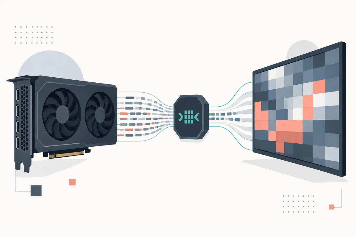
Modern consumer graphics hardware faces a relentless physical transmission wall. Driving an 8K 60 Hz display with 10-bit HDR or a 4K display at 240 Hz requires raw pixel bandwidths exceeding 40 Gbps. A 4K 144 Hz 10-bit RGB 4:4:4 panel demands approximately 25.8 Gbps of pure payload bandwidth; factoring in standard 8b/10b or 128b/132b physical-layer encoding overhead, blanking intervals, and audio channels pushes this beyond the native uncompressed limits of DisplayPort 1.4 and strains HDMI 2.1. In dual-panel virtual reality headsets and mobile form factors running over MIPI DSI interfaces, high transmission clock frequencies over flexible display cables also introduce severe electromagnetic interference (EMI) and unmanageable power dissipation.
To break this throughput bottleneck without adding perceptible display lag, display standards consortia developed Display Stream Compression (VESA DSC). Unlike distribution video codecs such as AV1 or HEVC, which utilize frame-level motion estimation, bidirectional temporal prediction, and deep discrete cosine transforms (DCT) to maximize bit efficiency at the cost of tens of milliseconds of latency and megabytes of memory, Display Stream Compression is an ultra-low-latency, intra-frame line-based compression standard. DSC executes natively in GPU display controllers (scanout engines) and display timing controllers (TCONs) in sub-microsecond timeframes. It guarantees visually lossless fidelity at typical compression ratios between 2:1 and 3.75:1, operates on fixed-rate allocations, and bounds line-buffer memory footprints to tens of kilobytes of on-die SRAM.
In modern unified silicon architectures, display engines reading high-resolution scanout framebuffers place relentless demand on memory crossbars, competing directly with GPU compute and accelerator workloads. Incorporating memory fabric efficiency concepts—similar to those detailed in Architecting Zero-Copy Heterogeneous Memory Fabrics for On-Device Multimodal AI in Consumer Silicon—is vital, but the physical display PHY lanes remain an insurmountable physical bottleneck without wire-protocol compression. Understanding how DSC functions inside modern silicon requires exploring its data pipeline: reversible colorspace transforms, adaptive prediction engines, indexed palettes, and hardware rate-buffer control loops.
The Physical Interconnect Bottleneck and DSC Architecture
Display Stream Compression (current revisions 1.1, 1.2a, and 1.2b) operates on the physical link between the GPU scanout engine and the sink panel's TCON. Rather than compressing framebuffers in system DRAM (which is handled by internal formats like Intel AxCC, AMD DCC, or Arm AFBC), DSC acts as a real-time transport codec right before physical-layer serialization (PHY).
+-------------------------------------------------------------------------------+
| GPU Display Scanout Engine                                                    |
|                                                                               |
|  +-------------------+       +--------------------+       +----------------+  |
|  | Framebuffer Read  | ----> | RGB -> YCoCg-R     | ----> | Slice Splitter |  |
|  | Engine (DRAM/VRAM)|       | Reversible Xform   |       | (1 to 16 cols) |  |
|  +-------------------+       +--------------------+       +-------+--------+  |
+-------------------------------------------------------------------|-----------+
                                                                    v
+-------------------------------------------------------------------------------+
| DSC Encoder Pipeline (Per Slice Engine in Silicon)                            |
|                                                                               |
|       +-----------------------------------------------------------+           |
|       |                                                           |           |
|       v                                                           v           |
|  +---------------------+   +---------------------+   +---------------------+  |
|  | Modified DPCM / MAP |   | Block Predictor     |   | Indexed Color Hist. |  |
|  | (Gradient Spatial)  |   | (Search 1-9 pixels) |   | (ICH 32-entry LUT)  |  |
|  +----------+----------+   +----------+----------+   +----------+----------+  |
|             \                         |                         /             |
|              +----------------> Target Selector <---------------+             |
|                                       | (Lowest Distortion / Flatness)        |
|                                       v                                       |
|                            +---------------------+                            |
|                            | Dynamic Quantizer   |<----+                      |
|                            +----------+----------+     | (Quantization        |
|                                       | Residual       |  Parameter QP)       |
|                                       v                |                      |
|                            +---------------------+     |                      |
|                            | Sub-Stream Mux      |     |                      |
|                            | (Entropy Coding)    |     |                      |
|                            +----------+----------+     |                      |
|                                       | Packed bits    |                      |
|                                       v                |                      |
|                            +---------------------+     |                      |
|                            | Rate Buffer FIFO    |-----+                      |
|                            | (Under/Overflow RCA)| Fullness Metric            |
|                            +----------+----------+                            |
+---------------------------------------|---------------------------------------+
                                        v
+-------------------------------------------------------------------------------+
| Physical Link Interface (DisplayPort Main Link / HDMI FRL / MIPI D-PHY/C-PHY)  |
+-------------------------------------------------------------------------------+
The compression process is partitioned into independent spatial regions called slices. A single display frame is divided vertically into one or more horizontal strips, and horizontally into two, four, eight, or sixteen slices. Slices are encoded and decoded concurrently by parallel hardware slice engines. Because each slice operates with zero cross-boundary data dependency, the maximum horizontal line-buffer memory in the decoder is divided by the number of horizontal slices, dramatically minimizing die area on low-cost panel TCONs.
Slice partitioning also provides error resilience: a bit-flip on the high-speed differential pairs only corrupts the remainder of that specific slice up to the next slice boundary, preventing multi-frame artifact propagation. The slice stream is packaged into fixed-size chunks that are transmitted across the DisplayPort Main Link (via secondary data packets and interleaved stream units) or HDMI Fixed Rate Link (FRL) character blocks.
How Display Stream Compression Encodes Pixel Data
DSC is an intra-line, prediction-based codec. It does not compute discrete cosine or wavelet transforms; instead, it processes pixels in groups of three (in DSC 1.1) or three/four (in DSC 1.2) across consecutive horizontal scanlines using three concurrent encoding paths: Modified Differential Pulse Code Modulation (mDPCM), Block Prediction, and Indexed Color History (ICH).
1. The Reversible Color Space Transform (YCoCg-R)
Before predictive spatial analysis occurs, the scanout engine converts 24-bit, 30-bit, or 36-bit RGB pixels into the YCoCg-R color space. While standard YCbCr transforms involve lossy floating-point or fixed-point matrix multiplications with round-off drift, YCoCg-R is an integer-reversible transformation that adds exactly one bit of precision to the chrominance channels without losing spatial entropy:
$$Co = R - B$$
$$t = B + \lfloor Co / 2 \rfloor$$
$$Cg = G - t$$
$$Y = t + \lfloor Cg / 2 \rfloor$$
The decoder reconstructs the RGB components bit-exact through an inverse sequence:
$$t = Y - \lfloor Cg / 2 \rfloor$$
$$G = Cg + t$$
$$B = t - \lfloor Co / 2 \rfloor$$
$$R = B + Co$$
De-correlating the color planes isolates luminance ($Y$) from the chrominance residuals ($Co, Cg$), permitting more aggressive quantization on color differences where human visual acuity is naturally low (contrast sensitivity function filtering).
2. Modified DPCM and Median-Adaptive Prediction
For standard continuous-tone photographic imagery, DSC uses Median-Adaptive Prediction (MAP). Let the current pixel be $X$, the left reconstructed pixel be $A$, the top reconstructed pixel be $B$, and the top-left reconstructed pixel be $C$. The predicted sample value $\hat{X}$ is formulated as:
$$\hat{X}_{MAP} = \min(A, B) \quad \text{if } C \ge \max(A, B)$$
$$\hat{X}_{MAP} = \max(A, B) \quad \text{if } C \le \min(A, B)$$
$$\hat{X}_{MAP} = A + B - C \quad \text{otherwise}$$
MAP detects whether a horizontal or vertical edge passes through the neighborhood and chooses either the horizontal or vertical neighbor to terminate gradient projection. The residual error $e = X - \hat{X}_{MAP}$ is then passed to the quantizer.
When a line begins or when high-frequency edges render the top reconstructor invalid, the engine falls back to a 1D left-pixel predictor ($e = X - A$) with modified clamping to maintain numerical stability within integer registers.
3. Block Prediction and Indexed Color History (ICH)
Natural images respond well to MAP, but synthetic consumer UI elements—such as black text on white backgrounds, desktop window frames, and CAD graphics—generate large residual spikes that destabilize adaptive quantizers. DSC mitigates this through two complementary mechanisms:
- Block Prediction: The encoder checks a historical window of 1 to 9 pixels within the current line buffer for repeating patterns. If a pattern matches within an error threshold, the entire pixel group is encoded purely as an offset displacement vector.
- Indexed Color History (ICH): The encoder maintains a running 32-entry Look-Up Table (LUT) of recently encountered 24-bit or 30-bit colors within the slice. When rendering crisp text or flat UI palettes, incoming pixels match existing ICH entries. If all pixels in a group match the history buffer, the encoder bypasses DPCM and quantization entirely, emitting 5-bit lookup indices.
// Conceptual representation of the DSC pixel evaluation path
typedef struct {
    uint16_t y, co, cg;
} PixelYCoCg;

typedef struct {
    uint8_t mode; // 0 = DPCM, 1 = BlockPred, 2 = ICH
    int16_t residual[3];
    uint8_t ich_index[3];
} EncodedGroup;

EncodedGroup evaluate_pixel_group(PixelYCoCg current[3], PixelYCoCg history_lut[32]) {
    EncodedGroup group;

    // Check Indexed Color History (ICH) for precise UI match
    if (match_ich_lut(current, history_lut, group.ich_index)) {
        group.mode = 2; // ICH Mode
        return group;
    }

    // Check Block Prediction (recurrent spatial shifts)
    if (evaluate_block_prediction(current, &group)) {
        group.mode = 1; // Block Prediction Mode
        return group;
    }

    // Default to Median Adaptive Prediction (DPCM Mode)
    group.mode = 0;
    for (int i = 0; i < 3; i++) {
        PixelYCoCg predicted = compute_map_prediction(i);
        group.residual[i] = current[i].y - predicted.y; // Quantizer scales this
    }
    return group;
}
Rate Buffer Control and Dynamic Quantization
The fundamental mechanical challenge of DSC is reconciling variable-length predictive coding with a strictly constant-bitrate (CBR) physical link. Unlike streaming codecs that absorb bitrate bursts across multi-second network buffers, DSC guarantees that neither the GPU's transmit FIFO overflows nor the display TCON's receive FIFO underflows, maintaining an end-to-end processing latency bounded to mere horizontal scanlines.
This is governed by the Rate Control Algorithm (RCA).
       Buffer Fullness (Bits)
          ^
Max (8KB) |-------------------------------------------- Buffer Overflow (Fatal)
          |                     / \
          |    Region 12-15    /   \     High QP: Aggressive Quantization
          |                   /     \    (Coarse detail, bits drop)
          |------------------/-------\----------------- Threshold High
          |                 /         \
          |    Region 4-11 /  Nominal  \  Medium QP: Balanced Fidelity
          |               /   Tracking  \
          |--------------/---------------\------------- Threshold Low
          |             /                 \
          | Region 0-3 /                   \--- Low QP: Fine Quantization
          |           /                         (Zero residual, bits climb)
   0 (Min)|----------/--------------------------------- Buffer Underflow (Stall)
          +---------------------------------------------> Time (Pixels Processed)
The rate buffer operates as a hardware FIFO. Bits generated by entropy-coded residuals or ICH indices enter the buffer at rate $R_{in}(t)$, while the physical link interface drains the buffer at a fixed clock rate $R_{out}$:
$$B(t) = B(t-1) + R_{in}(t) - R_{out}$$
The instantaneous buffer fullness is mapped into 16 distinct fullness regions (Regions 0 through 15). The RCA uses this region index to calculate the Quantization Parameter ($QP$), which scales the divisor applied to the prediction residuals:
$$QP = \text{clamp}\left(QP_{base} + \text{Offset}(Region) + \Delta_{activity} - \Delta_{flatness}, ; 0, ; QP_{max}\right)$$
- Buffer Tracking: If the buffer fills past safe operating margins (approaching Region 15), $QP$ increases exponentially. The quantizer truncates lower-order bits of the residuals, sharply decreasing $R_{in}(t)$ and arresting buffer growth before memory overflows.
- Flatness Detection: When consecutive pixels exhibit low variance, the engine flags a "flat" zone. If the quantizer were to apply a coarse $QP$ during a flat gradient, noticeable color banding would appear. The flatness detector forces the $QP$ down immediately, while the rate controller compensates by temporarily borrowing bits from future non-flat regions.
- Buffer Underflow Prevention: If the buffer approaches emptiness (Region 0), the encoder inserts deterministic stuffing bits to prevent the physical serializer from stalling.
The rate control FIFO operates as a deterministic, lock-free hardware queue. While software runtimes rely on synchronization patterns like Designing Lock-Free Shared-Memory Ring Buffers: Cache-Coherence, Memory Barriers, and Kernel-Bypass IPC, DSC implements this strictly in silicon registers using gray-coded read/write pointers across clock domains (the pixel clock $PCLK$ and the link symbol clock $LSCLK$).
Hardware Implementation: Sub-Stream Multiplexing and Decoder Line Buffers
The execution path of a DSC hardware engine is bound by high pixel clocks. For instance, a single 4K 120 Hz display requires an aggregate pixel rate of nearly 1.1 gigapixels per second. Consumer silicon cannot run an iterative entropy loop at 1.1 GHz without excessive dynamic power dissipation ($P = C V^2 f$).
To maintain manageable clock domains (typically 250 MHz to 350 MHz), the VESA standard specifies a parallel hardware architecture based on Sub-Stream Multiplexing (SSM).
       Quantized Residuals (Y, Co, Cg)
                     |
       +-------------+-------------+
       |             |             |
       v             v             v
  +---------+   +---------+   +---------+
  | Sub-    |   | Sub-    |   | Sub-    |
  | Stream  |   | Stream  |   | Stream  |
  | Enc 0   |   | Enc 1   |   | Enc 2   |
  +----+----+   +----+----+   +----+----+
       |             |             |
       | 16-bit      | 16-bit      | 16-bit
       | Words       | Words       | Words
       v             v             v
  +-------------------------------------+
  |   Sub-Stream Multiplexer (SSM)      |
  |   Barrel Shifter / Interleaver      |
  +------------------+------------------+
                     |
                     v Fixed-width Muxed Words
           [ Rate Control FIFO ]
                     |
                     v Native Bitstream
           [ PHY Serialization ]
Sub-Stream Multiplexing
Rather than passing all component data through a single serialization pipe, DSC 1.2 splits slice data into three or four independent sub-streams (one for $Y$, one for $Co$, one for $Cg$, and an optional fourth for alpha or block flags).
Each sub-stream encoder packs variable-length prefix codes and quantized residual mantissas into small 16-bit intermediate containers. The Sub-Stream Multiplexer sweeps across these buffers in round-robin sequence, packing full 48-bit or 64-bit words into the rate buffer. The decoder replicates this structure in reverse, permitting three independent hardware state machines to de-quantize color planes in parallel without mutual clock stalls.
Decoder Line-Buffer Memory Footprint
The ultimate design win for DSC in consumer electronics is the minimization of memory on the sink device. While desktop GPU display engines are built on advanced process nodes with plentiful SRAM, display TCONs are cost-optimized ASICs fabricated on legacy planar nodes (such as 40nm, 55nm, or 65nm).
Because DSC uses local predictors (left, top, top-left), the decoder only needs to retain the reconstructed pixels of the immediately preceding scanline. The exact SRAM line-buffer requirement per horizontal slice is defined as:
$$\text{SRAM Bits} = W_{slice} \times \text{BitsPerComponent} \times N_{components}$$
For an 8K display ($7680 \times 4320$) divided into 8 horizontal slices operating at 10-bit color:
$$W_{slice} = \frac{7680}{8} = 960 \text{ pixels}$$
$$\text{Line Buffer Size} = 960 \times 10 \times 3 = 28,800 \text{ bits } (\approx 3.6 \text{ KB per slice})$$
With 8 slice engines operating in parallel, the total decoder line-buffer SRAM footprint is under 30 KB. Compared to uncompressed frame-rate convertors or deep spatial buffers requiring 64 MB to 128 MB of off-die DRAM, DSC reduces the physical silicon area, pin count, and thermal profile of the panel controller.
This timing precision ensures that display engines maintain steady pixel cadence without frame stalling, fitting cleanly alongside Architecting Zero-Copy Asynchronous Execution Pipelines for On-Device Multimodal Models on Consumer Silicon.
Debugging and Verification in Silicon Pipelines
Implementing DSC across heterogeneous GPU architectures (Intel Xe-HPG, AMD RDNA, Apple Silicon, and NVIDIA Ada Lovelace/Blackwell) reveals non-obvious failure modes that do not manifest in traditional streaming codecs. Because DSC runs synchronous to display rasterization, software cannot hotfix line-drift during active scanout.
1. Slice Boundary Mismatches and Edge Seams
The most common artifact in early DSC silicon bring-up is the appearance of vertical seams at slice boundaries. This occurs when the encoder and decoder diverge in their reconstructed edge-padding models.
When a block prediction engine attempts to fetch a reference pixel across the left boundary of a slice, it must saturate the coordinate to the slice margin rather than wrapping into the adjacent slice memory. If an off-by-one register setting allows the predictor to sample stale data from an adjacent slice's right edge, the DPCM residual calculations cascade, producing bright color streaks spanning the entire horizontal width of the slice.
2. Rate Control Drift and Buffer Underflow
Because bits are stripped down to fractional rates (such as 8 bits per pixel from an uncompressed 24-bit source, achieving a 3:1 ratio), the rate buffer drain logic relies on a hardware Bresenham-style fractional accumulator. The accumulator drains $R_{out}$ bits per clock cycle:
// Hardware Bresenham fractional link drain accumulator
module dsc_drain_controller (
    input  wire        pclk,
    input  wire        rst_n,
    input  wire [7:0]  bpp_integer,       // e.g., 8 bits
    input  wire [15:0] bpp_fraction,      // e.g., 0.25 -> 16'h4000
    output reg  [7:0]  bits_to_drain
);

reg [15:0] frac_acc;

always @(posedge pclk or negedge rst_n) begin
    if (!rst_n) begin
        frac_acc      <= 16'h0;
        bits_to_drain <= 8'h0;
    end else begin
        {frac_acc}    <= frac_acc + bpp_fraction;
        // If the fractional accumulator overflows, step the drain rate
        if (frac_acc + bpp_fraction >= 17'h10000)
            bits_to_drain <= bpp_integer + 1'b1;
        else
            bits_to_drain <= bpp_integer;
    end
end

endmodule
If the GPU transmission side and the sink panel's TCON implement mismatched fractional link-drain step tables, the TCON's internal FIFO will slowly desynchronize. Over thousands of scanlines, this fractional drift causes an unrecoverable buffer underflow, which presents to the user as a temporary screen blanking or total display link retraining.
3. Flatness Detection Failures on High-Dynamic-Range (HDR) Text
With the deployment of 10-bit and 12-bit HDR displays, DSC engines must accommodate wide color gamuts (BT.2020) and high peak luminance. In HDR mode, a white cursor or text character sitting on an absolute black background produces a localized dynamic range delta far higher than standard dynamic range (SDR) interfaces anticipate.
If the flatness detector's noise threshold tables are not re-scaled for non-linear electro-optical transfer functions (such as SMPTE ST 2084 PQ), the engine misinterprets sharp HDR edge steps as noise patterns. The rate controller fails to engage low-$QP$ mode, resulting in severe chromatic ringing around high-luminance consumer UI elements. Resolving this requires hardware-level LUT adaptation in the GPU's display engine to map PQ luminance curves into perceptually uniform spaces before passing residuals to the DPCM pipeline.
| Metric / Parameter | VESA DSC 1.1 | VESA DSC 1.2a / 1.2b | Uncompressed Equivalent |
|---|---|---|---|
| Max Compression Ratio | 3:1 | Up to 3.75:1 | 1:1 |
| Native Color Format | RGB, YCbCr 4:4:4 | RGB, YCbCr 4:4:4, 4:2:2, 4:2:0 | RGB, YCbCr |
| Native Bit Depth | 8-bit, 10-bit | 8-bit, 10-bit, 12-bit, 16-bit | 8 to 16-bit |
| Slice Width Support | Multiples of 2 | Multiples of 4 or 8 | Entire scanline |
| ICH Palette Size | 32 entries | 32 entries (optimized packing) | N/A |
| End-to-End Latency | $< 1$ scanline ($< 5\mu\text{s}$) | $< 1$ scanline ($< 5\mu\text{s}$) | $0\mu\text{s}$ |
| Physical Interface | DP 1.4, HDMI 2.1 | DP 2.1 (UHBR), MIPI DSI-2 | All Physical PHYs |
Conclusion
Display Stream Compression bridges the gap between panel hardware and interconnect limits. As displays push to 8K, 16K, 360 Hz refresh rates, and multi-stream VR pipelines, uncompressed transmission across consumer cables becomes thermally and physically impractical.
Rather than relying on deep, high-latency video codecs that require significant frame storage, DSC executes with line-buffer level memory consumption, strictly bounded execution schedules, and deterministic rate buffers. By unifying reversible colorspace transforms (YCoCg-R), multi-modal prediction engines (mDPCM, Block Prediction, ICH), and high-throughput sub-stream multiplexing in silicon, modern GPU architectures can saturate next-generation displays with visually lossless fidelity, sub-microsecond latency, and predictable power profiles.
References
- VESA Display Stream Compression Standard Version 1.2a:
https://vesa.org/vesa-display-compression-codecs/ - VESA DisplayPort Standard Version 2.1a Specification:
https://vesa.org/featured-articles/vesa-releases-displayport-2-1-specification/ - IEEE Transactions on Circuits and Systems for Video Technology - Real-Time Ultra-Low-Latency Display Stream Compression Architectures:
https://ieeexplore.ieee.org/document/7497479